


What is a Resistivity Cable?
Resistivity cable is used for electrical resistivity sounding. It is a specialized cable designed for electrical resistivity tomography surveys.
What is a Resistivity Cable used for?
Multi electrodes resistivity cable works partnering with resistivity meter in water surveys, geological stratigraphy, landside studies, groundwater contaminations, mining detecting, archaeology, subsoil cavities detection, etc. Resistivity cable is suitable for the methodology of Electrical Resistivity Tomography (ERT, Electrical Imaging), Vertical Electrical Soundings(VES), Electrical Profiling(EP), Self Potential(SP) and Induced Polarization(IP).

What is resistivity sounding?
Vertical electrical soundings, such as Schlumberger soundings, are carried out by increasing the transmitting line AB step by step for increasing the depth of penetration of the MN reading made in the middle of AB. The apparent resistivity value obtained at each step is plotted as a function of AB/2, the plotting depth increasing from left to right.
What is the principle of IP methods?
The Induced Polarization (IP) phenomenon occurs with some types of minerals such as sulphide particles. When the pulse of the current is switched off, a decay curve of observed at the receiving electrodes. The M chargeability is a measurement of this decay.
Are there any practical matters for VES Sounding?
Let’s take the SYSCAL resistivity system for example. The SYSCAL resistivity meter is placed in the central part of the sounding.
The metallic electrodes have to be plugged into the ground as deeply as possible to decrease the ground resistance, for both the transmitting electrodes A, B, and the receiving electrodes M, N. If possible, water can be poured on the electrodes, or two electrodes can be set in parallel at each point to decrease this value. The wires going from the SYSCAL to the A, B electrodes have to be placed as far as possible from the wires going to the M, N electrodes to prevent insulation troubles.

The sounding start with small values of the AB line. From some values of the AB/2, two readings for different values of MN/2 have to be taken to check the lateral variations of the resistivity of the surface. Ideally, both resistivity values are identical.
The AB/2 values are logarithmically spaced( about 8 values par decade from 1 to 10, 10 to 100, 100 to 1000m, etc.). When the measurement becomes noisy(standard deviation Q greater than 5%), it is recommended to decrease the ground resistance of the A, B electrodes to drive more current, to increase the number of stackings and to repeat several times the same reading.
The apparent resistivity values have to be plotted on a bilogarithmic paper sheet, to check how the new reading compares with respect to the previous ones, before moving the A, B electrodes to the next measuring point. The data is stored in the internal memory of the resistivity meter after each reading. The depth of investigation is of the order of 20% of the length of the AB line.
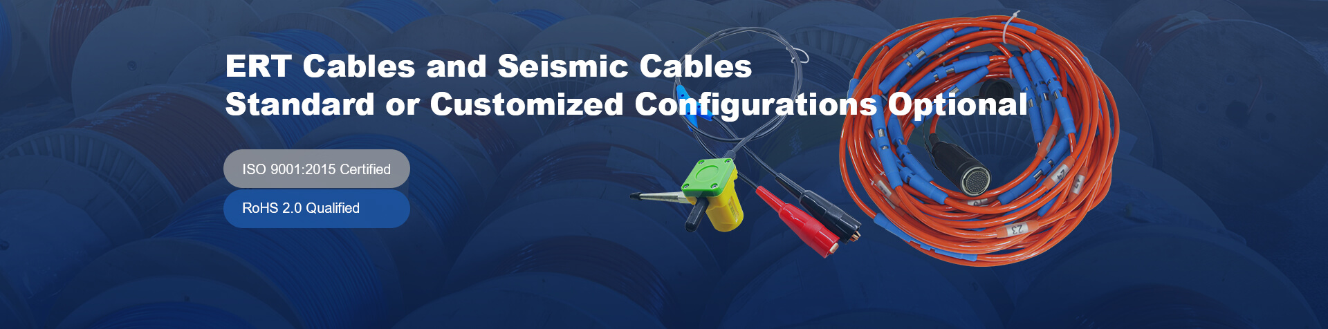
What does Seis Tech supply for resistivity sounding?
As a professional supplier, Seis tech supplies multi electrodes resistivity cables, reverse connectors, cable electrodes and cable jumpers for VES sounding. ST series of resistivity cables are made of high quality polyurethane, pure copper wires along with Kevlar, which made the resistivity cables with high tensile strength and high resistance to abrasion and frost. The resistivity cables supplied by Seis Tech could not only use for land surveys, but also for surveys in water areas, transition zones and borehole surveys.

Cable electrodes of the resistivity cable could be made of nickel wire, copper tube, stainless tube or phosphor bronze plate. And is very convenient to connect such cable electrodes to classical electrode pins by cable jumpers(cable to electrode jumpers). Besides, there is no need to use electrode pins when surveying in water and boreholes as the surface area of electrodes in ert cables has low contact resistance in such conditions.
Cable jumpers (cable to electrode connector) are designed for connecting electrode pins(external electrodes) to the cable system for resistivity survey. We supply cable jumpers with a different length which is as per the client’s requests. Assorted reliable connectors could be installed at one end or both ends of the ert cable. And we have cable connectors available for different resistivity systems i.e ABEM LS, ARES, PASI RM1, IRIS Syscal Pro, etc.


