




Analog Geophones vs Digital Geophones: What Are the Differences and When Does It Matter?
Analog and digital geophones represent the two dominant sensor architectures in land seismic acquisition. The analog geophone, a moving-coil velocity sensor, has served the industry for over 70 years. The digital geophone, built on MEMS accelerometer technology, emerged in the last two decades and has since expanded the operational limits of seismic recording.
Both convert ground motion into measurable signals, but they do so through fundamentally different physical principles, with different implications for survey design, data quality, and cost. This article examines how each technology works, where each excels, and how to choose between them for a given geophysical objective.
How an Analog Geophone Works
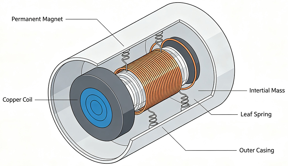
An analog geophone is a moving-coil electromagnetic transducer. A magnet is rigidly fixed to the geophone case. A coil wound around an inertial mass is suspended by leaf springs. When ground motion displaces the case, the magnet moves relative to the coil. By Faraday’s law of induction, the relative velocity between coil and magnet generates a voltage proportional to that velocity.
Mechanically, the geophone is a second-order spring-mass-damper system. Its transfer function in the frequency domain relates coil displacement $X$ to ground displacement $U$:
where ω₀ is the natural angular frequency, typically 4.5 Hz, 10 Hz, or 14 Hz for exploration geophones, and $\lambda$ is the damping coefficient, usually 0.6 to 0.7, set by an external shunt resistor. Above resonance, the geophone outputs a voltage proportional to ground velocity. Below resonance, sensitivity drops at 12 dB per octave. Near resonance, a phase shift of up to 180° is introduced, as documented by Hons and Stewart in their 2007 CREWES Research Report.
How a Digital MEMS Geophone Works
A digital geophone integrates a capacitive MEMS accelerometer with an Application-Specific Integrated Circuit (ASIC) running a closed-loop electrostatic feedback loop. The sensor uses a silicon proof mass suspended between fixed capacitor plates. Ground acceleration deflects the mass, altering the capacitance.
A high-frequency delta-sigma ($\Delta\Sigma$) feedback loop instantly applies an electrostatic force to counteract the movement, keeping the proof mass centered within nanometers. Because the mass remains virtually stationary, mechanical resonance is pushed above 1 kHz—well outside the seismic bandwidth. This delivers a flat amplitude and linear phase response from DC up to 800 Hz in the acceleration domain.
Side-by-Side Comparison
| Parameter | Analog Geophone | Digital MEMS Geophone |
|---|---|---|
| Sensing Principle | Moving-coil electromagnetic induction | Capacitive MEMS with closed-loop $\Delta\Sigma$ feedback |
| Measured Quantity | Ground velocity (above natural frequency) | Ground acceleration (from DC onwards) |
| Frequency Response | Rolls off below resonance; non-linear phase | Flat amplitude and zero phase shift across seismic band |
| Dynamic Range | Baseline range for single elements; scalable via arrays | High instantaneous dynamic range per single sensor |
| Power Requirements | Passive (Zero power consumption) | Active (Requires power per channel) |
| Tilt Sensitivity | Requires precise manual leveling to avoid distortion | Self-calibrating via the static gravity vector |
| Vector Fidelity (3C) | Dependent on mechanical assembly alignment | Guaranteed orthogonality (etched on a single silicon die) |
| EMI Immunity | Susceptible to line noise and induction | Immune (Digitized immediately at the sensor head) |
| Cost Profile | Economical per element for high-density layouts | Higher initial investment per sensor unit |
| Primary Deployment | High-channel count 2D/3D conventional surveys | Broadband 3C acquisition, microseismic, and strong-motion |
Why Analog Geophones Still Dominate Exploration
For conventional 2D and 3D reflection seismic surveys, arrays of analog geophones remain the industry default for three structural reasons:
1. Cost Efficiency at Scale
Large-scale land crews deploy tens of thousands of channels simultaneously. The per-channel hardware cost of MEMS digital sensors is significantly higher than analog alternatives. This makes analog arrays the economically rational choice for high-channel-count surveys where standard P-wave structural imaging is the primary objective.
2. Hardware-Based Noise Reduction
Wiring multiple analog geophones into localized strings forms a physical spatial filter. This array geometry attenuates coherent noise (like ground roll) and suppresses ambient, incoherent noise directly in the field before the signal ever reaches the recording unit.
3. Legacy Infrastructure Compatibility
The majority of legacy seismic recording platforms were engineered for analog geophone strings. Shifting to full digital networks requires updating line cables and central recording units. Seis Tech supplies elements maintaining seamless compatibility with major systems.
Where Digital Geophones Win
1. True Broadband Recording
MEMS sensors record down to DC with linear phase. They eliminate low-frequency roll-off and phase distortion near resonance, removing the need for post-acquisition phase compensation. For projects targeting deep lithological boundaries where low frequencies carry the critical signal, or for high-frequency microseismic monitoring, MEMS provides a uniform response.
2. Multi-Component (3C) Vector Fidelity
In a 3C digital sensor, the accelerometers are integrated onto a single silicon component, ensuring tight cross-axis orthogonality. Furthermore, the earth’s gravity vector provides an automatic reference for tilt measurement. In contrast, analog 3C geophones rely on the mechanical mounting of three separate moving-coil elements.
3. Near-Offset Clarity and Strong-Motion
The high instantaneous dynamic range of MEMS technology allows a single sensor to capture weak, deep reflections even in the presence of strong near-surface arrivals. Analog geophones typically require complex grouping to achieve comparable signal-to-noise separation in high-energy environments.
How to Make the Choice
The technical decision between analog and digital geophones balances three core parameters:
- Target Frequency Spectrum: Surveys requiring ultra-low frequencies for deep imaging or high frequencies for fracturing monitoring favor MEMS. Standard target windows are highly cost-optimized using analog.
- Channel Count and CAPEX: Large 3D exploration blocks with massive channel requirements leverage the cost benefits of analog strings to manage capital risk.
- Surface Noise Environment: High-ambient urban or industrial zones benefit from the physical spatial filtering of analog arrays on raw records, whereas accessible fields with low ground roll allow MEMS to maximize processing flexibility.
Related Products
References
[1] Hons, M.S. and Stewart, R.R. 2007. MEMS for the masses part 1: comparison to geophones in theory. CREWES Research Report, Volume 19.
[2] Mougenot, D. and Thorburn, N. 2004. MEMS-based 3C accelerometers for land seismic acquisition: Is it time? The Leading Edge, Volume 23, pages 246 to 250.
[3] Faber, K. and Maxwell, P.W. 1997. Geophone spurious frequency: what is it and how does it affect seismic data quality? Canadian Journal of Exploration Geophysics, Volume 33, pages 46 to 54.
[4] Krohn, C.E. 1984. Geophone ground coupling. Geophysics, Volume 49, pages 722 to 731.
[5] Brune, J.N. and Oliver, J. 1959. The seismic noise of the earth’s surface. Bulletin of the Seismological Society of America, Volume 49, pages 349 to 353.
[6] Wu, J. and Carley, L.R. 2001. Electromechanical $\Delta\Sigma$ modulation for high-Q MEMS accelerometers. Proceedings of the 14th IEEE International Conference on MEMS, pages 114 to 117.


