Geophones are used widely in seismic exploration, vibration monitoring, and structural health checks. To keep them reliable, their sensing elements need careful testing. This article takes a closer look at geophone element testing and explains how these tests are carried out in practice.
What Is Geophone Element Testing?
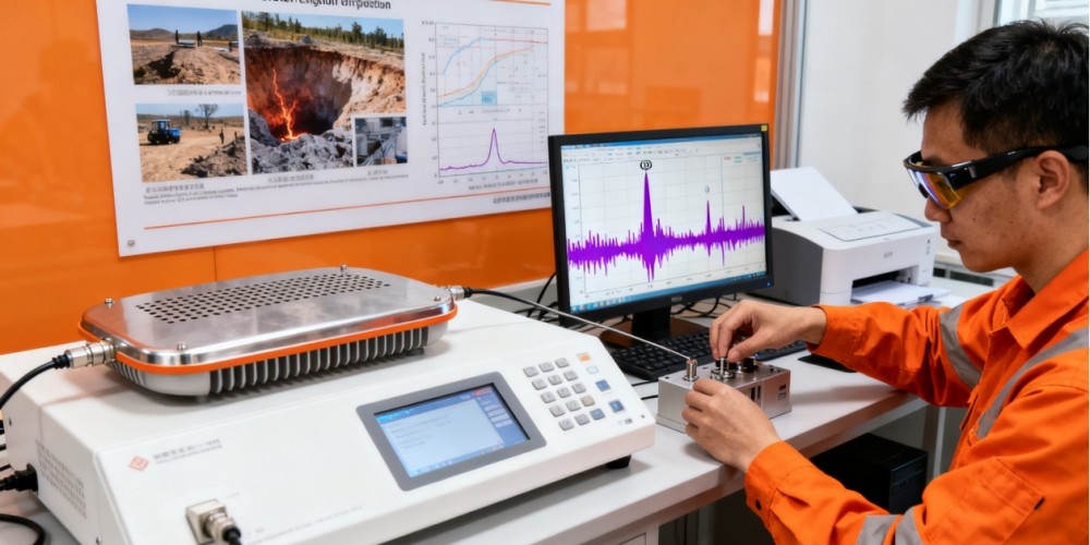
What Is Geophone Element Testing?
A geophone element is the sensing part of the device. It’s a moving coil suspended in a magnetic field that generates a voltage whenever the ground moves. Geophone element testing is a structured process that looks at the sensor’s electromechanical characteristics. These include frequency response, damping ratio, sensitivity, and electrical impedance.
The goal is to confirm the element meets its design specifications and can deliver accurate, repeatable, and stable measurements across its operating range. Such testing is especially important when geophones are deployed in harsh environments for seismic surveys, earthquake monitoring, or industrial vibration analysis.
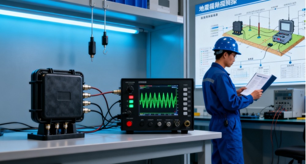
Why Test Geophone Elements?
Testing geophone elements is not merely a quality assurance step. It directly impacts data accuracy and the success of seismic or structural monitoring projects.
The main goals of geophone element testing include:
• Verification of Sensitivity: Ensuring that the geophone responds accurately to ground motion within its specified frequency range.
• Resonance Frequency Analysis: Identifying the natural resonance of the geophone to confirm proper design and performance.
• Damping Factor Evaluation: Checking the degree of damping, which affects how quickly the geophone settles after motion.
• Linearity and Distortion Testing: Confirming that the output voltage is proportional to velocity and free from significant non-linear distortions.
• Quality Control: Screening out faulty or degraded units before field deployment.
Methods of Geophone Element Testing
Geophone testing typically combines laboratory-based precision measurements with practical field tests.
Common approaches include:
1. Frequency Response Measurement
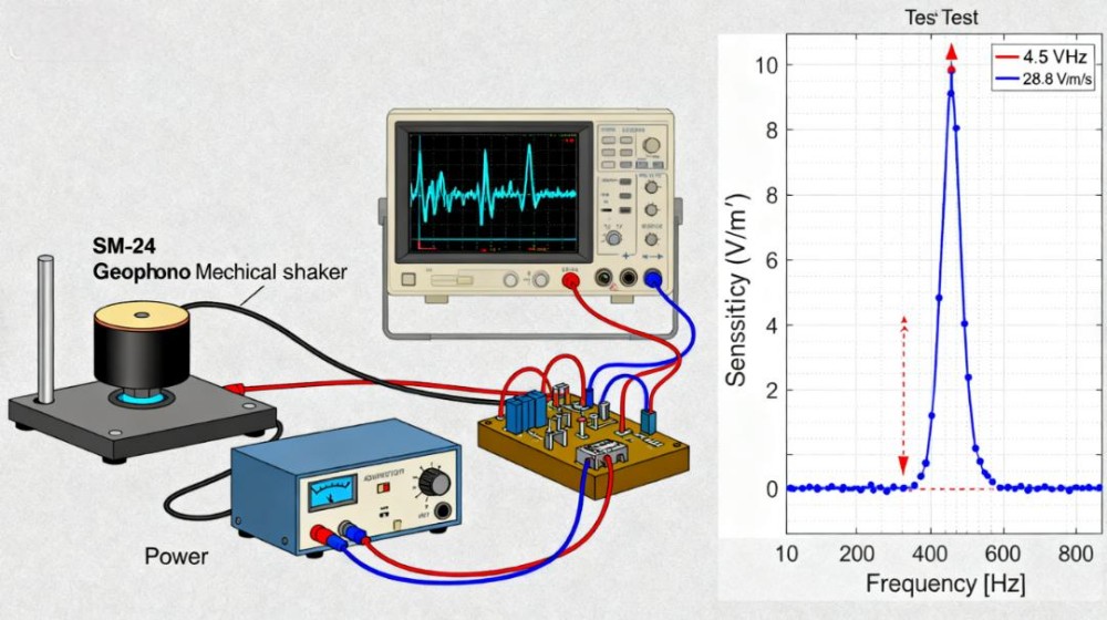
By applying a controlled vibration input with a precision mechanical shaker, the output voltage of the geophone is recorded across a wide frequency range. For example, an SM-24 geophone shows a sharp resonance peak at about 4.5 Hz and a sensitivity of around 28.8 V/m/s.
The frequency response curve highlights the resonance frequency, shows the usable bandwidth such as a flat response from 10 Hz to 200 Hz, and indicates overall sensitivity. These results help engineers compare performance across units and confirm the geophone element meets design tolerances.
2. Step Response Testing
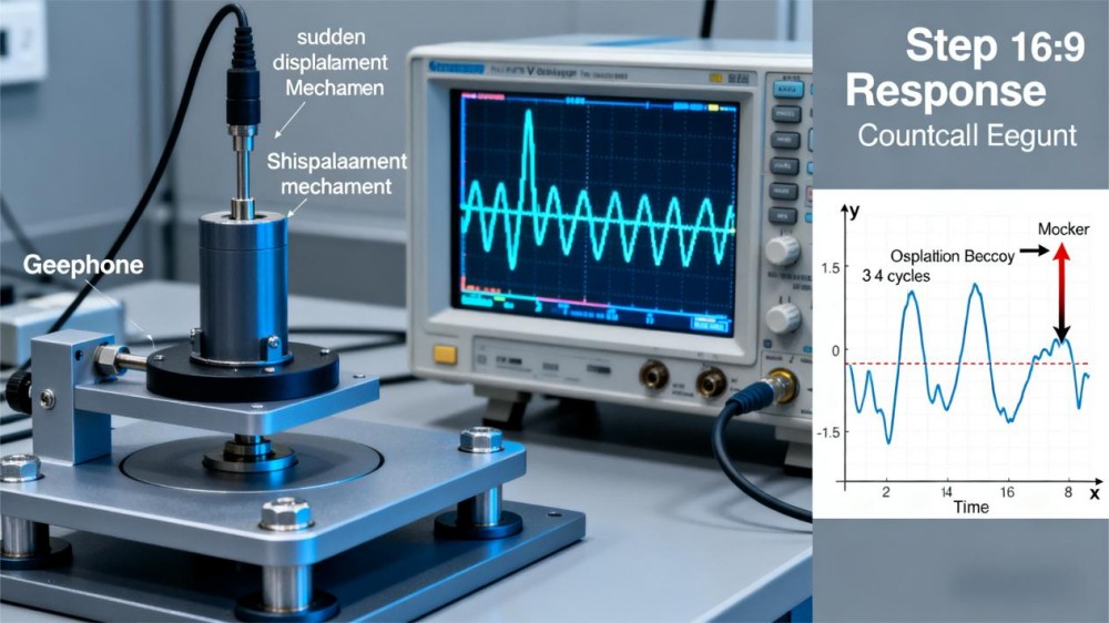
In step response testing, the geophone is subjected to a sudden displacement or vibration step and the output is tracked over time. For example, when the sensor is quickly moved and then released, the voltage response will rise sharply and then decay as the motion settles.
Engineers count how many oscillations occur before the signal stabilizes. They also measure how quickly the amplitude decreases to calculate damping and understand the transient behavior of the element.
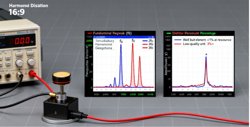
3. Harmonic Distortion Analysis
By applying sinusoidal vibrations at different frequencies, engineers can see if the geophone output contains harmonic distortion. For example, a well-built element may show less than 1% distortion at its resonance frequency, while a lower-quality unit might show 3% or more, which reduces accuracy in seismic data.
4. Noise Level Assessment
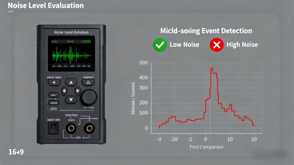
Intrinsic electrical noise is measured to determine the geophone’s signal-to-noise ratio. For example, a high-quality SM-24 geophone can have a noise floor as low as 10 nanovolts per root hertz at 1 Hz, which makes it suitable for detecting microseismic events.
If the noise level is higher, such as 50 nanovolts per root hertz, very weak signals can be lost in the background. This step is crucial for applications such as microseismic monitoring, where extremely small vibrations must be detected.
5. Electrical Parameter Testing
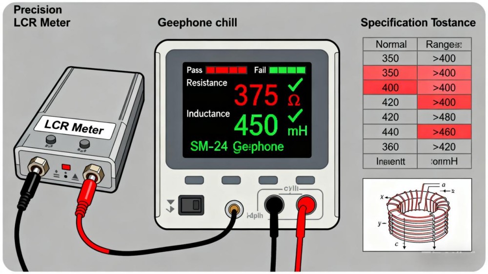
The coil resistance and inductance are measured using precision instruments. For example, an SM-24 geophone typically has a coil resistance of about 375 ohms and an inductance near 450 millihenries.
If resistance readings rise above 400 ohms or inductance drops well below the expected value, it can indicate damage, poor winding quality, or aging of the element. Deviations from specifications are strong indicators of manufacturing defects or deterioration that could affect long-term reliability.
Key Parameters in Geophone Element Testing
Several parameters define the performance of a geophone element:
| Parameter | Description | Typical Value |
| Natural Frequency (Hz) | The resonance frequency of the sensing element | ~4.5 Hz (SM-24) |
| Sensitivity (V/m/s) | Voltage output per unit velocity of ground motion | 28–30 V/m/s |
| Damping Coefficient | Controls overshoot and settling time in response to motion | ~0.7 |
| Distortion (%) | Level of harmonic distortion introduced | <1% for high quality elements |
| Noise Floor | Minimum measurable vibration above intrinsic noise | As low as 10 nV/√Hz |
Understanding and validating these parameters ensure reliable data collection.
Applications of Geophone Element Testing
Seismic Exploration
In oil and gas exploration, geophones must deliver highly accurate seismic data. Element testing guarantees that large arrays of geophones provide consistent measurements, minimizing errors in subsurface imaging.
Earthquake Monitoring
For seismology, tested geophones help detect faint precursors and aftershocks. Ensuring the sensitivity and noise floor is essential for early-warning systems.
Engineering and Infrastructure
Bridges, dams, and tall buildings are often instrumented with geophones to monitor structural health. Properly tested geophone elements ensure engineers can detect subtle vibrations before they become critical issues.
Industrial Vibration Monitoring
Machinery health monitoring relies on detecting abnormal vibrations. Tested geophones provide reliable data that can prevent costly downtime or mechanical failure.
Conclusion
Geophone element testing is a crucial process that ensures the accuracy, sensitivity, and reliability of geophones across seismic, industrial, and engineering applications. By verifying parameters such as resonance frequency, damping, and distortion, engineers can guarantee performance in demanding conditions.
Each geophone and every hydrophone supplied by Seis Tech will be tested and will be delivered along with a Calibration Certificate including testing result. Contact with our team for more detailed information.
References
- (1997). Geophone element testing. CREWES Research Report, 9(02). Retrieved from https://www.crewes.org/Documents/ResearchReports/1997/1997-02.pdf
- Sensor Nederland. (n.d.). SM-24 geophone specifications. Retrieved from https://sensor.nl
- Industry resources on seismic instrumentation and vibration monitoring.


