A geophone is a precision sensor that measures ground vibrations and translates them into corresponding electrical signals. These devices are widely used in geophysics, seismology, structural monitoring, and even DIY projects involving vibration detection.
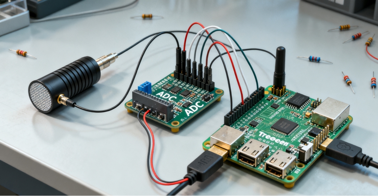
Since their analog output cannot be read directly by a Raspberry Pi, an Analogue-to-Digital Converter (ADC) is required to bridge the gap. We’ll walk through the hardware setup, wiring, and software you need to hook up a geophone to a Raspberry Pi with an ADC.
Geophone Basics
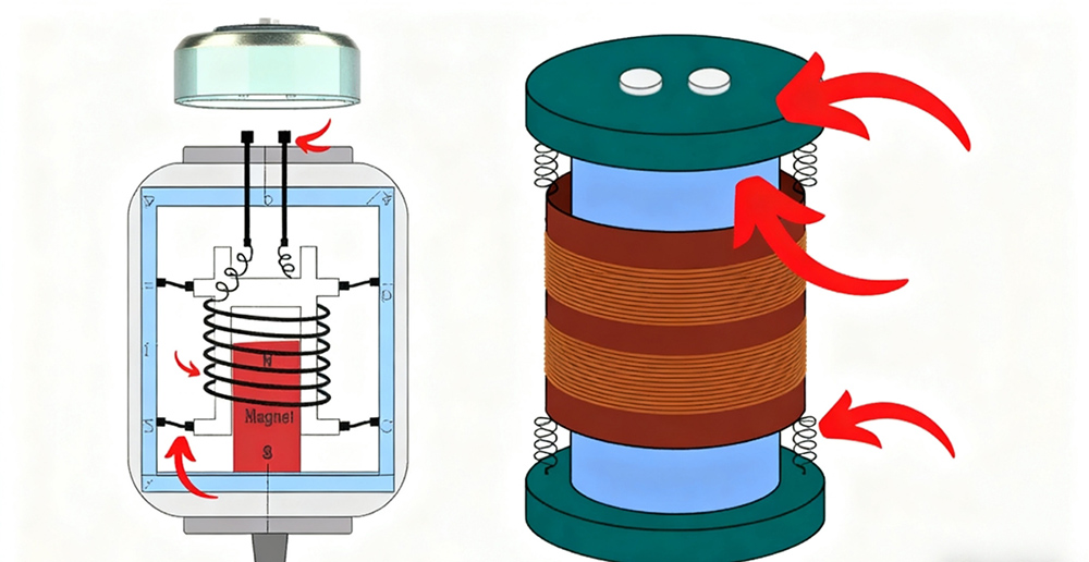
A geophone is a simple sensor made of a spring-mounted coil moving inside the magnetic field of a fixed magnet. When the ground shakes, the coil stays almost still due to inertia while the magnet moves with the ground, creating a changing voltage in the coil. This signal is a natural analog output that represents vibration. The SM-24 is a common model used worldwide in seismic surveys and monitoring.
Getting Started
What You’ll Need
• Raspberry Pi(any modern model with GPIO access)
• Geophone sensor(e.g., 4.5 Hz type)
• ADC module(such as MCP3008 or ADS1115)
• Resistors & capacitors(for signal conditioning, if required)
• Breadboard & jumper wires
• Python environment(pre-installed on Raspberry Pi)
Initial Setup
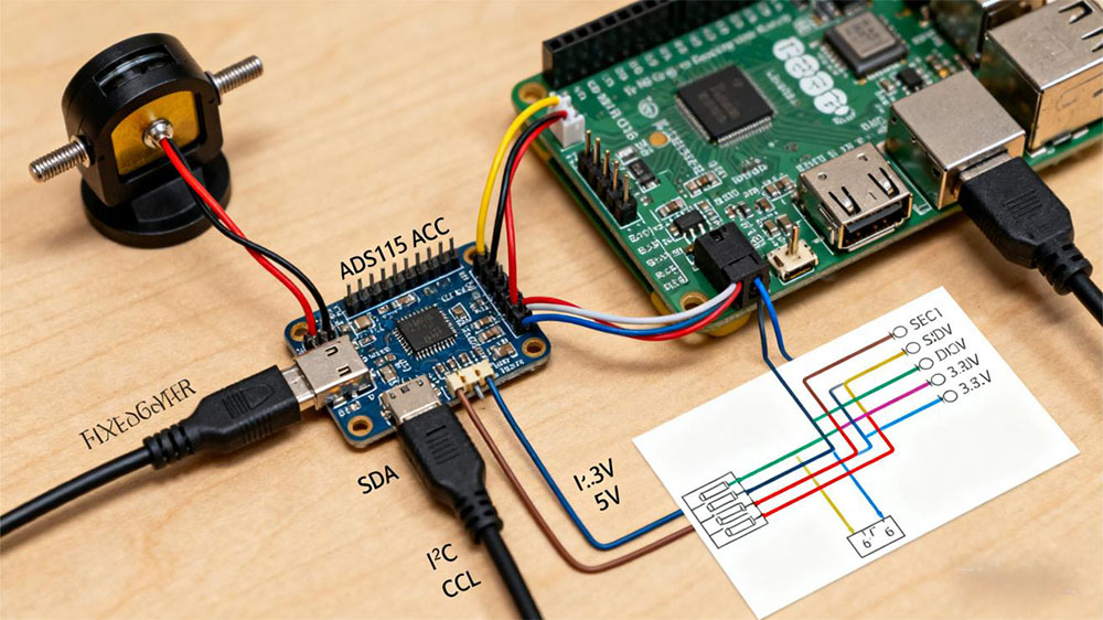
To set things up, wire the geophone’s output into the differential inputs of an ADC such as the ADS1115, which communicates with the Raspberry Pi over I²C. Power the ADC from the Pi’s 3.3V or 5V line, then link its SDA and SCL pins to the Pi’s I²C pins. Once I²C is enabled on the Raspberry Pi, you can use a Python library for the ADC to read the differential voltage coming from the geophone — this signal represents the ground vibrations being detected.
Step 1: Understanding the Geophone Signal
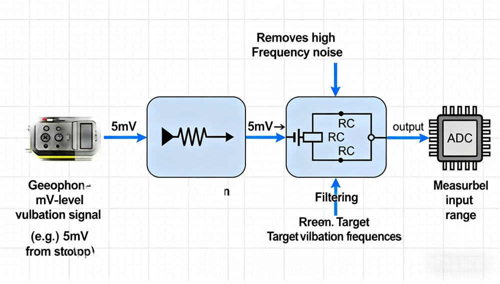
A geophone produces a very small analog voltage proportional to vibration—usually in the millivolt range. For example, a light footstep near the sensor might generate just a few millivolts.
To make such signals usable you typically need:
• Amplification– to scale the signal into the measurable input range of the ADC (e.g., boosting a 5 mV pulse up to hundreds of millivolts or more).
• Filtering– to remove high‑frequency noise and keep only the vibration frequencies of interest.
Without amplification, these faint signals are often too weak for the ADC to pick up reliably.
Step 2: Choosing an ADC
Since the Raspberry Pi lacks built-in analog input, an ADC module is required. An ADC converts the geophone’s millivolt-level analog signal into digital values the Pi can process.
Two widely used options are:
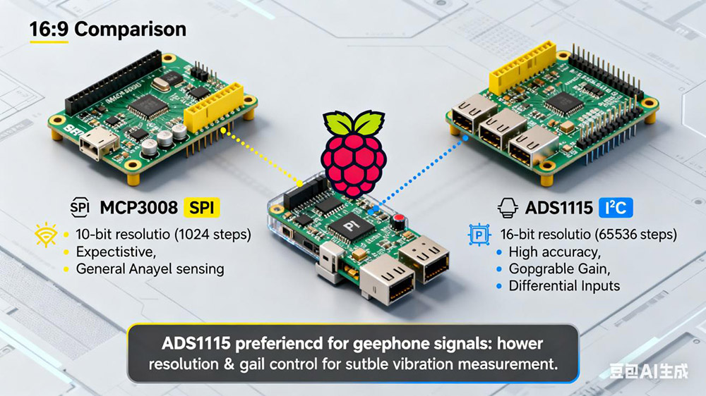
• MCP3008: 10‑bit resolution (1,024 steps), communicates over SPI. It is inexpensive, easy to wire, and works well for general analog sensing when precision is not critical.
• ADS1115: 16‑bit resolution (65,536 steps), communicates over I²C. It offers much higher accuracy and also supports differential inputs and programmable gain, which can be very helpful for very small geophone signals.
For vibration detection, the higher resolution and gain control of the ADS1115 are usually preferred, since geophone output signals are subtle and require fine measurement precision.
Step 3: Wiring the System
Connect the geophone outputto the ADC input. Because geophone signals are weak, you may include an op‑amp stage in between for amplification and noise reduction.
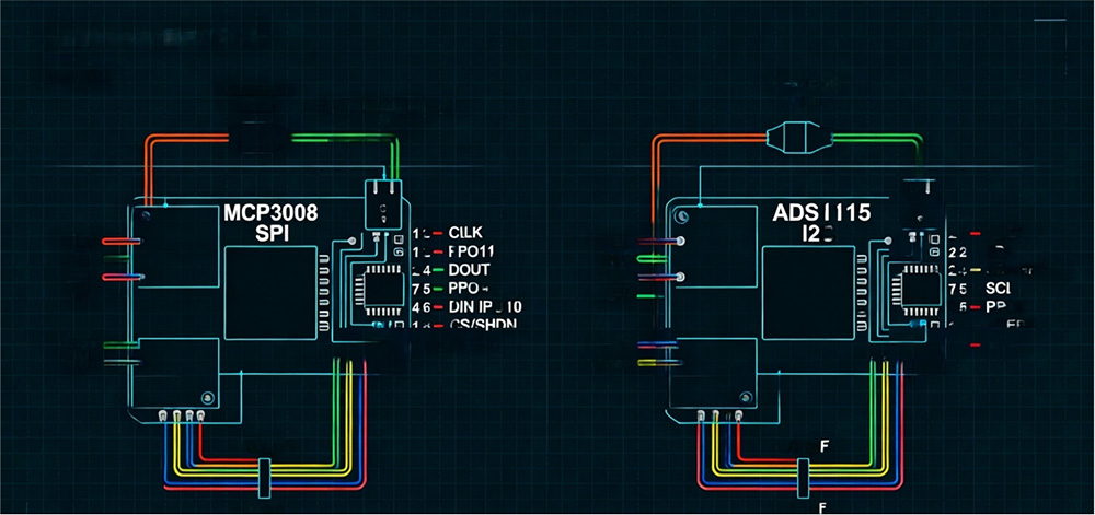
Connect the ADC to the Raspberry Pi GPIO:
• MCP3008(SPI): connect VDD to 3.3V, VREF to 3.3V, AGND to GND, CLK to GPIO11 (SCLK), DOUT to GPIO9 (MISO), DIN to GPIO10 (MOSI), CS/SHDN to GPIO8 (CE0).
• ADS1115(I²C): connect VDD to 3.3V, GND to GND, SDA to GPIO2 (SDA), SCL to GPIO3 (SCL). Optional ADDR pin can be tied to GND or VDD to set the I²C address.
Use proper decoupling capacitors (e.g., 0.1 µF ceramic near VDD and GND) to stabilize the ADC supply.
Keep analog signal wires short and twisted together if possible, to minimize noise pickup.
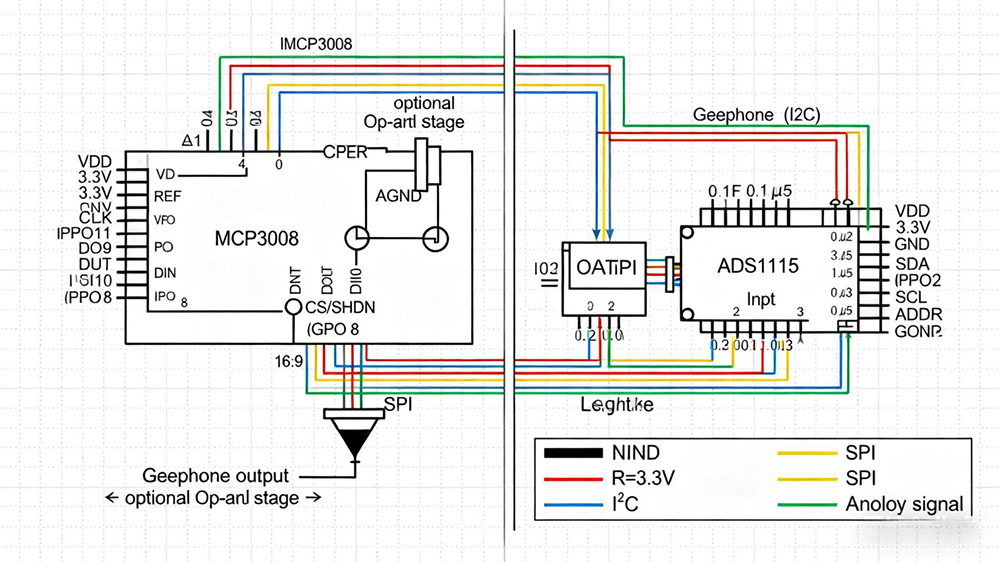
For detailed wiring instructions and diagrams, refer to the official datasheets for the MCP3008 and ADS1115.
Step 4: Installing Python Libraries
Install the necessary Python packages for interfacing with the ADC:
• sudo apt update
• sudo apt install python3-pip
• pip3 install adafruit-circuitpython-ads1x15
For MCP3008:
• pip3 install adafruit-circuitpython-mcp3xxx
Step 5: Reading Data from the Geophone
Here is a basic Python example using an ADS1115:
• import time
• import board
• import busio
• import adafruit_ads1x15.ads1115 as ADS
• from adafruit_ads1x15.analog_in import AnalogIn
# Initialize I2C bus
i2c = busio.I2C(board.SCL, board.SDA)
# Create ADS1115 object
ads = ADS.ADS1115(i2c)
chan = AnalogIn(ads, ADS.P0)
while True:
print(f”Voltage: {chan.voltage:.6f} V”)
time.sleep(0.1)
This script continuously reads and prints the voltage from the geophone. With proper amplification, you should see clear voltage fluctuations corresponding to vibrations.
Step 6: Signal Processing
Once the raw signal is available, you can apply a wide range of techniques to make sense of the data:
• Fourier analysis: Break down the signal into its frequency components to identify vibration modes, resonances, or seismic wave types.
• Filtering: Use digital filters (low‑pass, high‑pass, band‑pass) to isolate specific frequency bands, such as removing background noise while keeping structural vibration frequencies.
• Data logging: Store time‑series data in CSV, databases, or cloud platforms for later review and long‑term monitoring.
• Event detection: Define thresholds to automatically trigger alerts when vibrations exceed safe levels, useful for earthquake early‑warning or machinery fault detection.
• Advanced processing: Apply windowing functions, moving averages, or wavelet transforms to study transient events or subtle vibration patterns.
Python libraries such as NumPy, SciPy, pandas, and visualization tools like Matplotlib or Plotly can support these tasks. For more complex real‑time analysis, frameworks such as TensorFlow or PyTorch can be used to build machine learning models for pattern recognition and anomaly detection.
Applications
• Seismic activity monitoring
• Structural health monitoring of bridges, buildings, or machinery
• Educational experiments on wave propagation
• DIY vibration sensors for security or robotics
Conclusion
By interfacing a geophone with a Raspberry Pi through an ADC, you can build a powerful, low-cost vibration monitoring system. Proper amplification and filtering ensure reliable signal capture, while Python enables extensive real-time analysis.
Seis Tech is specialized in offering assorted geophones, hydrohpones and vibration monitoring solutions. These velocity geohones and piezo hydrophones are designed for researchers, engineers, and industry professionals who need reliable and scaled vibration detection.
By combining hardware expertise with powerful software, Seis Tech provides reliable sensors for seismic surveys, industrial vibration monitoring, structural health monitoring and educational applications. Please feel free to reach our our team for more professional information.


