




How to Choose the Right Geophone for Geophysical Research
Selecting the right geophone is essential for obtaining reliable seismic data. The sensor directly affects signal quality, frequency response, noise performance, and the accuracy of geophysical interpretation. Different research applications require different geophone characteristics. A sensor suitable for ambient noise tomography may not be the best choice for shallow engineering surveys, while a high-frequency geophone designed for near-surface exploration may not capture low-frequency seismic signals effectively. This guide explains the key factors to consider when choosing a geophone, including natural frequency, sensitivity, damping, sensor configuration, and environmental requirements.
What Is a Geophone?
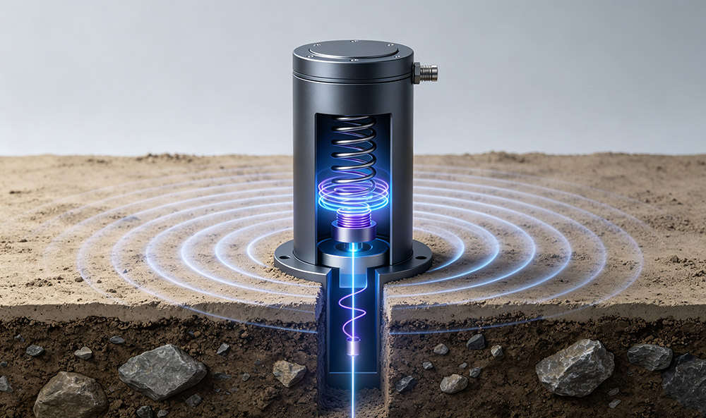
A geophone is an electromechanical seismic sensor that converts ground velocity into an electrical signal. Most traditional geophones use a moving-coil design. Inside the sensor, a coil is suspended within a magnetic field by a spring system. When seismic waves cause the ground and sensor housing to move, the relative motion between the coil and magnet generates an electrical output proportional to ground velocity.
Because geophones are velocity sensors, their performance depends strongly on the mechanical design of the internal mass-spring system. Important parameters such as natural frequency, damping ratio, and sensitivity determine how accurately the sensor records seismic signals across different frequency ranges. Modern seismic acquisition systems still widely use geophones because they provide reliable performance, stable calibration characteristics, and cost-effective deployment for large sensor arrays. Recent research continues to improve geophone performance through low-frequency compensation, advanced materials, and new sensor designs.
Key Specifications When Selecting a Geophone
When choosing a geophone for geophysical research, the most important specifications include:
- Natural frequency
- Sensitivity
- Damping ratio
- Frequency response
- Spurious frequency
- Component configuration
- Environmental durability
Each parameter affects the final quality of seismic data.
1. Geophone Natural Frequency
What Is Geophone Natural Frequency?
Natural frequency (f₀) is the resonant frequency of the geophone’s internal mass-spring system. It determines the lower end of the sensor’s effective frequency response. A lower natural frequency allows the geophone to detect slower ground motion, while a higher natural frequency provides better response to high-frequency signals. However, a lower natural frequency does not always mean better performance. The selected frequency must match the seismic source, target depth, and expected signal bandwidth. Recent seismic sensor studies emphasize that natural frequency should be evaluated together with sensitivity, noise level, and the complete acquisition system rather than being considered alone.
Low-Frequency Geophones (1 Hz to 5 Hz)
Low-frequency geophones are designed for applications where detecting long-period ground motion is important. Typical applications include:
- Ambient Noise Tomography (ANT)
- Earthquake monitoring
- Passive seismic networks
- Surface-wave dispersion studies
- Regional seismic research
These sensors provide better response to lower-frequency seismic energy, making them suitable for studies involving weak natural vibrations and deeper geological structures. However, low-frequency geophones generally require more careful installation because their mechanical systems can be more sensitive to tilt and environmental conditions.
Standard Geophones (10 Hz to 14 Hz)
10 Hz and 14 Hz geophones are among the most commonly used seismic sensors for active-source surveys. They are widely applied in:
- Seismic refraction surveys
- Reflection surveys
- MASW (Multichannel Analysis of Surface Waves)
- Engineering geophysics
- Near-surface geological investigations
The popularity of 10 Hz geophones comes from their balanced performance between sensitivity, bandwidth, mechanical stability, and field practicality. For many land seismic applications, a 10 Hz geophone provides sufficient frequency response without the additional installation challenges associated with very low-frequency sensors.
High-Frequency Geophones (28 Hz to 100 Hz)
High-frequency geophones are designed for shallow targets where higher resolution is required. Common applications include:
- Shallow engineering surveys
- Pavement and infrastructure studies
- Blast vibration monitoring
- Structural health monitoring
- Small-scale geological investigations
Because these sensors respond strongly to higher-frequency signals, they are useful when the target produces short-wavelength seismic energy. However, they are not suitable for applications requiring detection of low-frequency seismic waves.
How to Match Geophone Frequency to Your Application?
A general selection guide is shown below:
| Application | Recommended Natural Frequency | Typical Sensor Type |
|---|---|---|
| Ambient Noise Tomography | 1 Hz to 5 Hz | 1C or 3C geophone |
| Earthquake Monitoring | 1 Hz to 4.5 Hz | 3C geophone |
| Surface Wave Analysis (MASW) | 4.5 Hz to 14 Hz | Vertical 1C geophone |
| Seismic Refraction | 10 Hz to 14 Hz | Vertical 1C geophone |
| Shallow Engineering Survey | 28 Hz to 100 Hz | 1C or 3C geophone |
| Microseismic Monitoring | 1 Hz to 5 Hz | 1C or 3C geophone |
The correct frequency depends on the relationship between the sensor response and the dominant frequency of the seismic signal. A common mistake is selecting a geophone only based on the lowest possible frequency. In practice, the sensor must provide a suitable balance between frequency response, sensitivity, noise performance, and field conditions.
2. Geophone Sensitivity
What Is Geophone Sensitivity?
Sensitivity describes the electrical output generated by a geophone when exposed to ground velocity. It is normally expressed as: V/(m/s) or Volts per meter per second. A higher sensitivity geophone produces a stronger output signal from the same ground motion. Typical sensitivity values include:
- 20 V/m/s.
- 28.8 V/m/s.
- 40 V/m/s.
- 82 V/m/s.
- 100 V/m/s.
- 260 V/m/s.
- 650 V/m/s.
The appropriate sensitivity depends on the application and recording system.
Why Does Sensitivity Matter?
Higher sensitivity is especially useful when measuring weak seismic signals, including:
- Ambient seismic noise
- Microseismic events
- Low-energy surface waves
- Distant earthquake signals
However, sensitivity should not be considered separately from the entire acquisition system. A very sensitive sensor connected to an unsuitable digitizer may introduce signal clipping or reduce measurement efficiency. Researchers should evaluate:
- Sensor sensitivity
- Digitizer input range
- System noise level
- Expected vibration amplitude
The effective recording bandwidth depends not only on the geophone specification but also on whether the sensor output remains above the noise floor of the acquisition system.
3. Geophone Damping Ratio
What Is Damping in a Geophone?
Damping controls the movement of the internal mass after the sensor receives a seismic impulse. Without sufficient damping, the internal system may continue oscillating, causing ringing effects and inaccurate waveform recording. Proper damping improves:
- Frequency response stability
- Phase accuracy
- Transient response
- Signal quality
Most traditional geophones operate with damping ratios typically around 0.5 to 0.7 of critical damping. A properly damped geophone provides a more accurate response, especially for:
- Seismic inversion
- Surface-wave analysis
- Frequency-domain processing
- Waveform comparison studies
4. Spurious Frequency and Signal Quality
A professional geophone should not only provide the correct frequency response but also maintain signal accuracy across the operating bandwidth.
What Is Spurious Frequency?
Spurious frequency refers to unwanted resonance behavior outside the primary measurement direction of the geophone. This can occur because of mechanical limitations, internal component movement, or imperfect isolation between sensing elements. If a spurious resonance appears within the seismic acquisition bandwidth, it may create artificial peaks in frequency analysis and affect interpretation results. For research applications, the spurious frequency should normally be significantly higher than the target operating range. This is particularly important for:
- Spectral analysis
- Surface-wave inversion
- Seismic attribute studies
- High-resolution waveform processing
Harmonic Distortion
Harmonic distortion describes unwanted signal components generated by the sensor itself. Low harmonic distortion is important because seismic research often depends on accurate waveform preservation. Applications that require good waveform fidelity include:
- Seismic interferometry
- Ambient noise analysis
- Full waveform inversion
- Laboratory seismic experiments
High-quality research geophones are typically designed to minimize harmonic distortion and maintain a stable response over their operating frequency range.
1C vs 3C Geophones: Which Configuration Is Better?
One of the most important decisions when selecting a geophone is choosing between a single-component (1C) sensor and a three-component (3C) sensor. The correct choice depends on whether the project requires only vertical ground motion measurement or complete three-dimensional particle motion analysis.
What Is a 1C Geophone?
A 1C geophone measures seismic motion along one axis. In most land seismic applications, the sensor is installed vertically and records the vertical component of ground velocity. Advantages of 1C geophones include:
- Lower cost
- Simple installation
- Easy deployment in large arrays
- High efficiency for active seismic surveys
Common applications include:
- Seismic refraction
- Seismic reflection
- MASW surveys
- Near-surface engineering investigations
For large-scale surveys where hundreds or thousands of sensors are required, 1C geophones are often the most practical solution.
What Is a 3C Geophone?
A 3C geophone contains three orthogonal sensing elements:
- Vertical component (Z)
- Horizontal component (X)
- Horizontal component (Y)
This configuration measures complete three-dimensional ground motion. 3C geophones are commonly used for:
- Earthquake monitoring
- Microseismic monitoring
- Shear-wave analysis
- Wave polarization studies
- Borehole seismic surveys
- Seismic tomography
The additional horizontal components allow researchers to analyze:
- Wave arrival direction
- Particle motion
- P-wave and S-wave characteristics
- Anisotropy effects
Recent seismic monitoring research continues to use multi-component sensors because they provide more complete information about complex wavefields compared with single-component measurements.
1C vs 3C Geophone Comparison
| Feature | 1C Geophone | 3C Geophone |
|---|---|---|
| Measurement direction | One axis | Three axes |
| Installation complexity | Simple | More careful orientation required |
| Cost | Lower | Higher |
| Data information | Vertical or single direction | Full particle motion |
| Best for | Large seismic arrays | Detailed wavefield analysis |
For routine engineering surveys, 1C geophones are often sufficient. For research projects involving seismic wave behavior, earthquake studies, or advanced processing methods, 3C geophones usually provide significantly more information.
Geophone Installation and Environmental Considerations
Sensor performance depends not only on specifications but also on deployment conditions. Even a high-quality geophone can produce poor data if installation is incorrect.
Surface Deployment
For land seismic surveys, important considerations include:
Ground Coupling
Good coupling between the geophone and the ground is essential. Poor coupling may reduce high-frequency response and introduce unwanted noise. Common installation practices include:
- Firm insertion into soil
- Proper spike placement
- Avoiding loose material around the sensor
- Stable orientation during recording
Weather Protection
Field environments may expose sensors to:
- Rain
- Dust
- Mud
- Temperature changes
- Mechanical impact
A durable housing and reliable cable system improve long-term field performance.
Borehole Geophone Applications
Borehole geophones are designed for more demanding environments. They may require:
- Pressure-resistant housings
- Compact mechanical design
- High-temperature tolerance
- Reliable cable assemblies
- Directional stability
Typical applications include:
- Downhole seismic monitoring
- Oil and gas exploration
- Reservoir monitoring
- Deep geological studies
Unlike surface sensors, borehole geophones must maintain stable operation under mechanical pressure and restricted installation conditions.
Cable and Connector Requirements
The cable system is an important part of seismic data reliability. A high-quality geophone should be paired with cables designed for field conditions. Important considerations include:
- Water resistance
- Tensile strength
- Temperature stability
- Connector reliability
- Long-distance signal transmission capability
For large seismic arrays, cable failure can create significant maintenance costs and data gaps. Common professional systems use ruggedized connectors designed for repeated field deployment.
Recommended Geophone Selection Guide
The following table provides a practical reference for common geophysical applications.
| Research Application | Recommended Frequency | Recommended Configuration | Key Requirements |
|---|---|---|---|
| Ambient Noise Tomography (ANT) | 1 Hz to 5 Hz | 1C / 3C | High sensitivity, low-frequency response |
| Earthquake Monitoring | 1 Hz to 4.5 Hz | 3C | Accurate three-component recording |
| Surface Wave Analysis (MASW) | 4.5 Hz to 28 Hz | 1C Vertical | Stable phase response |
| Engineering Refraction | 10 Hz to 40 Hz | 1C Vertical | Reliable field deployment |
| Microseismic Monitoring | 1 Hz to 5 Hz | 3C | Directional wave analysis |
| Shallow High-Resolution Survey | 28 Hz to 100 Hz | 1C / 3C | High-frequency response |
| Borehole Monitoring | 4.5 Hz to 100 Hz | 3C | Rugged housing and stability |
Common Mistakes When Selecting a Geophone
Choosing Frequency Based Only on Price
The cheapest geophone is not always the most economical option. A sensor that does not match the seismic target may produce poor-quality data, increasing processing time and reducing research value.
Assuming Lower Frequency Is Always Better
A lower natural frequency provides better response to slow ground motion, but it may not provide the best resolution for shallow high-frequency targets. Frequency selection should always be based on the survey objective.
Ignoring the Data Acquisition System
The geophone and seismograph work as one measurement system. Sensor output, seismograph resolution, noise level, and sampling rate should be considered together.
Selecting 1C Sensors for Multi-Directional Studies
If the research requires particle motion analysis or wave polarization information, a 3C geophone is usually the appropriate choice. Using only vertical sensors may limit the ability to interpret complex seismic signals.
Frequently Asked Questions About Geophones
What frequency geophone should I use for seismic surveys?
- For general near-surface seismic surveys, 10 Hz to 14 Hz geophones are commonly used.
- For passive seismic monitoring and earthquake studies, lower-frequency sensors between 1 Hz and 5 Hz are generally preferred.
- For shallow high-resolution investigations, higher-frequency geophones may provide better results.
Are 3C geophones better than 1C geophones?
Not necessarily. A 3C geophone provides more information because it measures three directions of ground motion, but it also costs more and requires more complex deployment. The best choice depends on the research objective.
What sensitivity should a research geophone have?
There is no single ideal sensitivity value. Higher sensitivity is useful for weak signals, but the sensor must match the acquisition system and expected ground motion levels.
How should I choose a geophone for MASW?
MASW surveys commonly use vertical geophones in the 4.5 Hz to 14 Hz range. The final selection depends on survey depth, target frequency, spacing, and required resolution.
How long can a geophone operate?
A professional geophone can operate for many years when properly installed and protected. Long-term performance depends on mechanical design, environmental exposure, cable quality, and maintenance practices.
Why Choose Geophones from Seis Tech?
Selecting a geophone is not only about choosing a sensor with a specific frequency rating. A reliable seismic measurement system requires the right combination of sensor performance, mechanical design, environmental protection, and application suitability. At Seis-Tech, we focus on providing professional seismic sensor solutions for research institutions, geophysical exploration companies, and engineering applications.
For more information about Seis-Tech geophones and seismic sensor solutions, visit: https://www.seis-tech.com/
A properly selected geophone improves not only field data quality but also the reliability of subsequent processing, interpretation, and research conclusions.
Final Thoughts
Choosing the right geophone requires a balance between technical specifications and practical field requirements. Natural frequency determines the sensor’s response range, sensitivity affects signal strength, damping influences waveform accuracy, and sensor configuration determines the type of seismic information that can be recorded. For active-source seismic surveys, a standard 10 Hz to 14 Hz vertical geophone is often an effective choice.
For passive source monitoring, earthquake studies, and advanced research applications, low-frequency or three-component geophones may provide better results. The most suitable geophone is not necessarily the most advanced or expensive model.
It is the sensor that best matches the seismic objective, environmental conditions, and data quality requirements. By carefully evaluating these factors before deployment, researchers and engineers can improve seismic data reliability and achieve more accurate geophysical interpretations.
References
Academic and Technical References
- Bhatti, H. S., Aizzuddin, A. M., Hadeed, M., Vorathin, E., & Mohamad, H. (2024). Review of fibre optic geophones and accelerometers for potential application in seismic acquisition for carbon storage monitoring. Optics & Laser Technology, 177, 111015.
- Dean, T., & Grant, M. (2024). A beginner’s guide to seismic sensors. Preview, 230, 38–
- Yang, D., Yang, T., Wang, Y., & Liu, D. (2024). Development of improved short-period geophone: Implementation of low-frequency compensation. Measurement, 234, 114799.
- Liu, Y., Li, Y., & Wang, Z. (2023). Advances in seismic sensor technology and applications for distributed geophysical monitoring. Sensors, 23(15), 6821.
- Zhang, H., Wang, J., & Chen, X. (2022). Optimization of seismic acquisition parameters for high-resolution near-surface geophysical investigations. Geophysical Journal International, 230(2), 945–
Industry and Technical Resources
- International Association of Geophysical Contractors (IAGC). (2022). Seismic Acquisition and Data Quality Guidelines.
- Society of Exploration Geophysicists (SEG). (2023). Seismic Data Acquisition and Processing Technical Resources.
- Institute of Electrical and Electronics Engineers (IEEE). (2021). Standards and practices for seismic instrumentation and sensor performance evaluation.


